
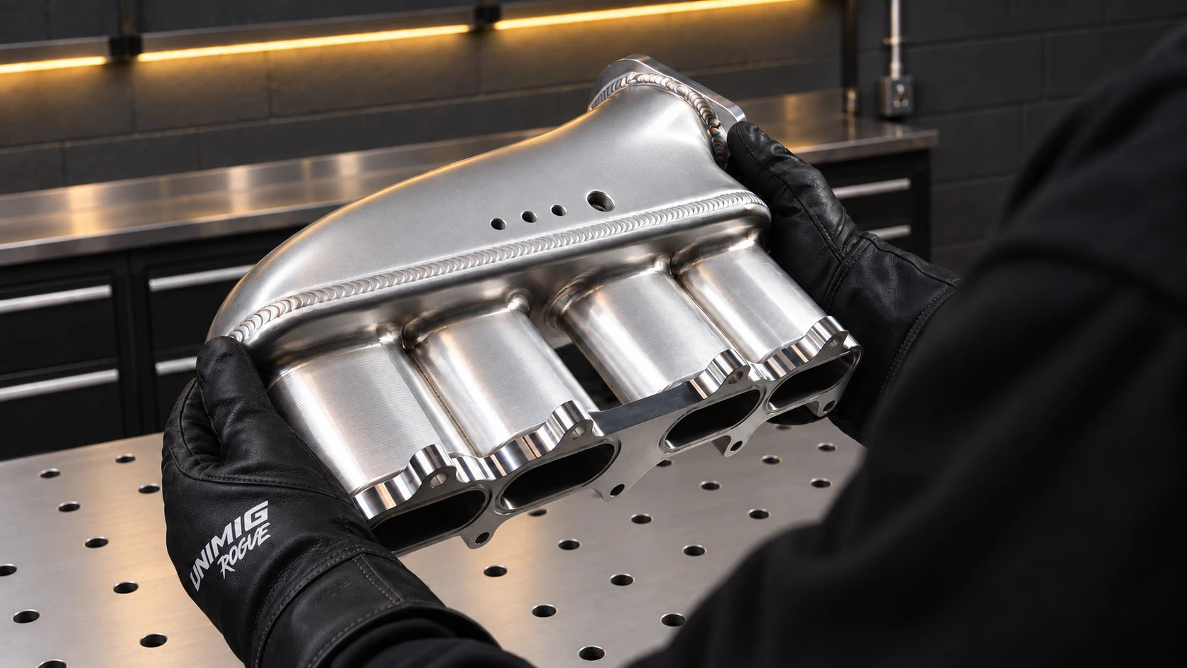
Aluminium can be welded successfully once the alloy, filler and process are matched to the job. It still presents heat, radiation, fume and fire hazards; aluminium grinding dust also needs appropriate controls.
Quick Navigation
Jump to:
Metal Grades
There are a few types of aluminium filler wire, but the most common ones you can get are 4043 and 5356. Both of these fillers are aluminium alloys, with 4043 containing 5% silicon and 5356 containing 5% magnesium.
- Choose filler from the identified base alloy, joint and service requirements using the filler maker's selection chart.
- 4043 and 5356 are common but not interchangeable. Neither is suitable for every alloy in a whole series.
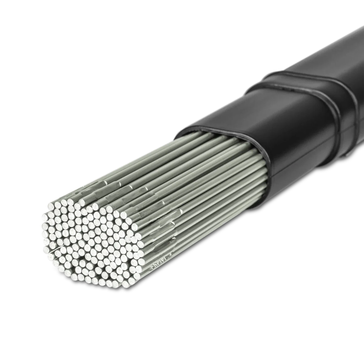
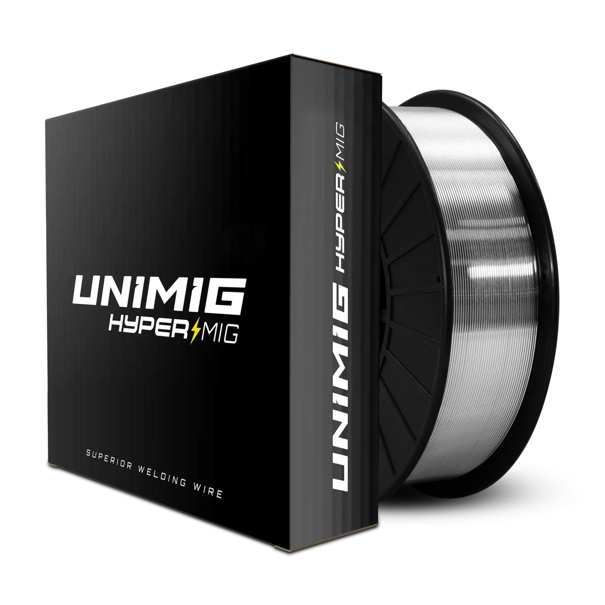
Do not use 4043 for a high-magnesium 5xxx alloy merely because it is aluminium. Also check elevated-temperature service restrictions on magnesium-bearing fillers such as 5356.
Hot Shortness
Aluminium is ‘hot short’, which means that it’s prone to cracking when it’s close to its melting point. Basically, as the weld cools, aluminium is more likely to crack. It usually starts where the weld has ended and will often spread down the entire length of the weld. Cracks in your weld are bad news, and you’ll need to redo it because they’re structurally weak.
Metal Preparation
When it comes to aluminium, preparation is super important. Aluminium is not forgiving at all; anything left on it will mess up your weld.
Any dirt, paint, oil or otherwise needs to be completely removed, and that’s just the first part of cleaning it. Aluminium also has a layer of oxide on it which needs to be cleaned off.
There are a few ways that you can clean off this oxide layer. The first is with a handheld wire brush. Select a brush that you can dedicate to aluminium only because using a brush that you’ve previously used on steel or stainless can contaminate the aluminium.
A shiny surface is not proof that oxide and contamination have been removed.
Use a dedicated stainless-steel brush or an appropriate aluminium-preparation tool without embedding contamination or excessively smearing the surface.
Use suitable abrasive type, speed and pressure; do not treat every powered brushing method as prohibited.
The original photograph is no longer available. The named equipment and surrounding information have been retained.
Remove oil and grease first with a suitable cleaner, allow it to dry, then remove oxide mechanically. Solvent cleaning does not by itself remove the oxide layer.
Keep in mind that you don’t need to go too crazy with the cleaning because no matter how well you try to clean this off, it’s never going to be perfect.
Oxide reforms rapidly, so weld promptly after proper preparation and protect the cleaned surface. The process's cleaning action does not replace removing contamination first.
If you’re TIG welding aluminium, giving your filler rod a quick wipe down doesn’t hurt either.
It sounds like a hassle, but cleaning your aluminium thoroughly is critical because of the metal’s melting points. The arc will still ignite even if the metal is dirty or still has its oxide layer. However, if you leave too much of the oxide layer on the aluminium, you might not be able to start a weld pool.
Pure aluminium melts at about 660°C while aluminium oxide melts at a much higher temperature; alloys have their own melting ranges. This difference makes proper oxide removal important.
MIG Welding Aluminium
MIG welding aluminium can be a lot faster than using TIG, and you can stick to your standard DC settings, so you won’t need a machine with AC/DC capabilities.
However, welding aluminium on MIG is like ‘pushing a wet noodle through a straw’ if you’re using the standard torch. It is possible, but it can be really hard and incredibly frustrating.
Aluminium is a softer metal than steel and stainless, so trying to feed it through a torch lead becomes much more difficult because it bends easier.
There are a few ways to combat this with your MIG torch.
Select a compatible liner, guides, drive rolls and contact tip for the aluminium wire and torch. Installation dimensions are specific to that system.
You’ll need to make sure you’ve got U-groove rollers, as these will grip the aluminium better and help stop birdnesting. Lastly, you can get aluminium specific contact tips, which will also help with the wire feeding.
The second thing to do is try and keep your torch as straight as possible when you’re welding. The shorter torch you have, the easier this is (and the shorter the travel distance for the aluminium), but it does get tricky if you have a 3 or more metre torch. Big loose curves or loops can be ok, but any tight circles are almost definitely going to kink your wire.
Argon is commonly used for aluminium MIG and TIG. Approved argon/helium mixtures are another option for some procedures; do not use the steel MIG gas by default.
Install and secure the spool with power isolated using the feeder's specified adaptor, locating feature and brake arrangement.
Sometimes this will work, but you must have the correct setup. Otherwise, you’re going to run into birdnesting.
What to do if your wire keeps birdnesting
What exactly is a birdnest anyway? What does it look it? Great questions.
A birdnest in your wire happens at the drive rollers. It occurs when the rollers are pushing the wire through the torch, but somewhere along the line it’s being stopped, so it’s not coming out the end of your torch.
The wire’s still being pushed, though, so it has to go somewhere. That somewhere is all around your drivers, where it tangles and loops over itself and looks a bit like a loose bird nest.
There are a few things you can check if your wire does birdnest, but even if you check everything, it might not work.
Change your liner
Let’s go back to our ‘wet noodle in a straw’ idea. You want your straw to be as hospitable to your noodle as you can make it. To do that, you’ve installed a new Teflon liner into your torch, which you’ve done for two reasons. One, it’s slipperier and offers less resistance against the aluminium. Two, pushing your aluminium through a liner that’s had steel in it can contaminate it.
Make sure you keep your straw as straight as possible. If you think about those crazy curly straws you got as a kid, there’s no chance a wet noodle would push through that, regardless of how slippery it is.
That’s why it’s super important your torch stays straight, and you also don’t accidentally kink it in your hands while you’re moving around. Even if you can’t see it, the liner in the torch will hold some of those small bends itself even if the torch isn’t bent.
Isolate the welder before removing the torch or changing its liner.
Change your guide tube
Fit the polymer liner and any separate guide parts shown in the torch manufacturer's diagram.
Keep the torch cable straight while setting the liner length.
Trim and secure the liner using the specified dimensions, rather than a universal flush-cut rule.
Reassemble completely before restoring power, then thread wire with hands clear of moving parts and the wire outlet.
Check your consumables
Once the feeder is assembled, use its approved threading mode with hands clear of the drive rolls and wire outlet.
Remove and refit the nozzle and tip only with output safely isolated, where the threading procedure requires it.
Use the contact tip and drive groove marked for the intended wire and application. A nominal wire-size marking does not mean the tip bore is exactly that diameter.
That’s why aluminium specific consumables are the best to use; they’re drilled just a bit bigger to accommodate for the fact that the wire swells with the heat.
A lot of the time, you’ll be able to run the wire all the way through the lead and out the tip without issues. It’s once you put your tip and nozzle back on and try to weld with it that you start seeing problems.
Check your tensions
If your torch is straight and you fed your wire through without a contact tip, but when you tried to weld it failed, check the tension on your wire.
Use the minimum drive pressure that feeds reliably under the manufacturer's test. Investigate restrictions before increasing pressure on soft aluminium wire.
Now you’ve fixed the tension on your wire, fed the wire back through the torch, no problems there. You’re ready to weld. Your wire birdnests again. This is usually the point people start pulling their hair out at, but there’s one last thing you can check to try and fix the problem.
Fit the spool, adaptor and retaining parts in the feeder's specified arrangement.
Set spool braking to prevent overrun without excessive drag; the retaining nut is not the brake adjustment on every feeder.
An aluminium conversion kit must match the specific feeder and torch. Check its parts list; not every torch needs a neck spring or the same guide arrangement.
If a standard torch cannot feed reliably after correct setup, compare a compatible spool gun or push-pull system for the workload.
Spool gun
A spool gun shortens the wire path but still needs compatible drive parts, a clear guide or liner and correct pressure settings.
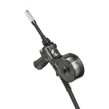
Setting up your spool gun is relatively simple, and most of the process is pretty similar to setting up your standard MIG torch.
Isolate power before disconnecting the torch or handling wire at the feeder. Secure the remaining spool end and remove wire as the manual directs.
Check torch, control and gas connections against the exact machine; a matching-looking connector alone does not establish compatibility.
The next step is to attach your wire spool. This, again, is done pretty much the same way as with a normal torch:
- Unscrew the nut and lift the plastic casing off
- Release the spool brake
- Slide your spool onto the shaft
- Feed the first part of the wire through the inlet guide (found at the bottom) and between the drive rollers
- Reapply the spool brake
- Put the plastic casing back on and re-screw the nut
Spool guns are pre-loaded with U-groove rollers, but just remember that if you change your filler wire thickness, you might need to change those rollers to match.
Select spool-gun mode where the machine requires it, using the approved gun and control settings.
Follow the spool gun's threading procedure, keeping hands clear and isolating output before refitting front-end parts.
Even though the setup is the same, welding aluminium with a spool gun requires a bit of a different technique to get it right. You’ll need to increase your travel speed.
Start with the wire and machine's aluminium setup guidance for the actual diameter, gas and joint.
If using a synergic mode, select the correct aluminium wire and gas programme.
Trial the settings on representative material and check fusion as well as bead appearance.
Do not use an arbitrary 11 V or 13 V setting as a general aluminium starting point.

Tips for your aluminium MIG weld
1. Use the right technique
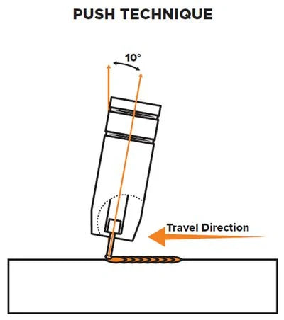
A push angle is commonly recommended for aluminium MIG to maintain shielding ahead of the pool.
Maintain the procedure's angle and extension; pulling does not make penetration physically impossible, but can change shielding and bead characteristics.
However, if you push, the argon gas can properly shield the molten weld pool and keep it clean.
2. Thoroughly clean your metal
MIG welding aluminium is naturally a dirtier process than TIG welding it and a thin layer of black soot on the weld is normal, as well as a bit of spatter, but too much soot is a problem.
Cleaning your aluminium thoroughly and making sure it is spick and span is just as crucial on MIG as it is for TIG.
3. Get the gas flow right
If soot is excessive, check surface preparation, correct gas, leaks, nozzle condition, torch angle and flow at the torch. Do not automatically increase flow before diagnosing the cause.
Don’t go too crazy with the gas though, you’re not going to be able to get rid of all the soot no matter how high it is, and too much gas will give you an erratic arc. Plus, it’s wasteful.
If soot persists after the basic checks, inspect the gas path and confirm gas quality with the supplier. Do not use a higher flow reading as proof of adequate shielding.
4. Fill in the ends
When you finish an aluminium weld, you’re often left with a crater or ‘fisheye’ at the end. This looks like a round dent, and it can cause a few issues if it isn’t filled in.
Use the machine's crater-fill function where available, or the procedure's controlled finishing technique, to avoid leaving an underfilled crater.
Practise that finish on scrap; uncontrolled pausing or repeated retriggering is not a universal crater-repair method.
If you leave your crater unfilled, you may find that your weld cracks after some time. This is especially true for any welding done to trailers or anything that’s subject to constant vibration.
An unfilled or cracked crater can be a local weakness. Its significance depends on the joint, loading and acceptance requirements.
When you end a weld, whether you’re making tacks or running a joint, your aluminium wire will usually form a small ball. You’ll need to cut this off before you start your next weld.
MIG can be productive on aluminium, including thin material with suitable equipment and procedures. There is no universal 2 mm lower limit or requirement to change to TIG below it.
TIG Welding Aluminium
TIG welding aluminium is arguably harder, but there are more options to play with that will affect (and probably improve) the weld than there are with MIG. It’s definitely a slower process feeding the wire in by hand yourself, but you can get finer, nicer looking welds with it.
As with all TIG welding, the first thing you need to do is choose and prepare your tungsten.
Choose tungsten using the AC power-source recommendation. Modern inverters commonly use lanthanated or other approved electrodes; zirconiated is not automatically best on every machine.
| Electrode | Application notes |
|---|---|
| Lanthanated | Common AC/DC option on suitable inverters; identify the actual oxide content and current range. |
| Ceriated | Often useful at lower current; use the maker's AC/DC guidance. |
| Zirconiated | Principally an AC choice; not automatically best for every inverter. |
| Thoriated | Traditionally used for DC; not universally excluded from AC. Thorium requires appropriate handling and dust controls. |
| Mixed oxide / rare earth | Composition varies by product. Colour alone does not establish equivalence. |
Select diameter and tip preparation for current, waveform and polarity. This replaces an unsupported dot-rating chart.
Now that you’ve picked a tungsten, you’ll need to prepare it for the weld. The rule used to be that if you were welding aluminium, you’d need to ball the tip of your tungsten (mostly because operators used to mainly use a pure tungsten).
Conventional transformer AC and modern inverter AC may need different electrode preparation.
For an inverter, use the recommended point or truncated point and electrode type; do not assume the preparation is identical for every machine.
A tip may round during AC welding, but the acceptable shape depends on electrode type and waveform. Splitting or uncontrolled melting is not normal operation.
You can influence how much your tungsten tip balls by changing your amps and AC balance settings.
AC is the usual choice for manual aluminium TIG because it provides cleaning action. Specialised DC procedures exist, so aluminium TIG is not always AC.
AC Balance
AC stands for Alternating Current. When you’re using DC, you can choose if you’re using a negative or positive current. In AC, you get both. It flows between negative and positive in a ‘cycle’.
You can, however, choose how much time will be spent in positive and how much time will be spent in negative. This is your AC balance.
The original photograph is no longer available. The named equipment and surrounding information have been retained.
The positive and negative currents have their own properties, which is why some welds may require different percentages of positive to negative.
The electrode-positive part assists oxide cleaning and heats the tungsten more; electrode-negative time favours workpiece heating. These are relative effects, not an on/off division of heat.
Use the manufacturer's starting balance and confirm whether the display means EN%, EP% or a relative adjustment. Clean material may need less EP cleaning time.
A 50/50 balance can form a weld pool and has been used on conventional AC equipment. More EN may improve electrode capacity and concentration on suitable inverters, but select balance for the actual setup.
Besides your lack of penetration, upping your cleaning means you spend longer in the positive part of your AC cycle. The longer you spend in the positive, the hotter your tungsten gets.
Excessive electrode-positive time can overheat the tungsten. If the tip deforms or melts, stop and check balance, current, electrode size and shielding.
AC-balance adjustment is a model feature, not something to assume across an entire brand.
Find the balance control in the exact model manual.
Automatic recommendations, where provided, are starting settings that still need to suit the joint and electrode.
An older model's −5 to +5 scale must not be read as a universal EN or EP percentage. Verify what increasing the displayed value does on your machine.
AC Frequency
The AC balance is not the only setting that affects your weld. The frequency of your cycle also plays a role in how your weld is going to turn out. While your balance determines how long you spend in the positive and negative currents per cycle, your frequency will determine how many cycles are completed per second.
Conventional transformer output commonly follows supply frequency: 50 Hz in Australia. Inverter AC frequency can be controlled independently where the machine supports it.
Available frequency ranges vary by model; use the actual manual rather than a blanket 20–200 Hz range.
Frequency changes arc concentration and sound. Bead profile also depends on current, balance, joint and travel speed.
A higher frequency is usually recommended for thinner metals, as the arc is tighter, so you can be more accurate in thin joints (like outside corners).
Assess noise and use suitable hearing protection; sound exposure is not determined by the selected frequency alone.
Tips for your aluminium TIG weld
The actual process of TIG welding aluminium is basically the exact same as TIG welding steel or stainless. Start your arc, form a weld pool and feed in your filler rod. There are, however, some things that are different.
1. Get a foot pedal
Being able to control your amps is really helpful for making a good aluminium weld. While you can program in start amps, up slope, peak amps, down slope and finish amps, using a foot pedal is probably the easiest way to weld aluminium.
A compatible foot pedal or torch remote can adjust current during the weld if the power source supports it.
Tapering current and adding the appropriate filler can help finish the crater. Post-flow protects the hot weld and electrode from oxidation; it does not itself prevent solidification cracking.

2. Make sure the cleaning is happening
You can see the cleaning happening when you begin a weld, as the top oxide layer almost looks like snow melting off the ground as the metal heats up.
The etched zone beside an AC TIG weld indicates cleaning action; its presence alone does not prove the weld is sound.
It’s a good sign and gets wider or narrower depending on your AC balance. It can be cleaned off at the end of your weld with a wire brush with no issues.
3. Let the puddle form
You will need to wait until the weld puddle has fully formed and you have a shiny pool before you begin adding your filler metal. Because of the cleaning action that happens at the start, it may take some time. Give your weld a few seconds to form a proper puddle before you start dabbing in filler.
4. Watch the heat
Like MIG welding, you’ll generally need to move along the joint faster than you would with steel. If your metal is getting too hot and you have a foot pedal, then you can back off your amps a bit to help bring the heat back down.
If heat is excessive, correct current, travel, sequencing or cooling intervals within the procedure. Adding filler solely as a coolant is not a substitute for controlling heat input.
5. Finish strong, not harsh
Once you reach the end of your weld, as well as easing off your amps slowly to prevent cracking, you can also add some extra filler metal to fill in the crater that would otherwise form. If you’re using a torch, setting your finish amps lower than your peak is recommended; you don’t need to keep your amps full blast on the edge of your metal.
The original photograph is no longer available. The named equipment and surrounding information have been retained.
The original photograph is no longer available. The named equipment and surrounding information have been retained.
Troubleshooting Your Aluminium Welds
Is your metal clean?
Start by checking preparation, then investigate shielding, filler, electrode and settings rather than attributing every fault to dirt.
Soot, porosity, oxide inclusions and peppering have overlapping causes. Cleaning is important, but may not be the whole remedy.
Check your gas
If you’re getting a thick ring of black soot around your bead when MIG welding and your aluminium is as clean as you can get it, then it’s most likely a gas problem.
Confirm the specified gas and delivery at the torch. Argon is common, but the approved procedure may use another suitable mixture; excess flow can disturb shielding.
If that doesn’t help, your gas might be contaminated, or there could be a leak. If it’s contaminated gas, then you’ll need a whole new cylinder. If your gas hose is leaky, then you’ll need to replace it.
A light soot deposit does not prove the joint is sound or that gas has cleaned it. Inspect the weld to the required acceptance criteria.
Maintain your contact tips
While we’re on common problems you get when MIG welding, let’s talk about contact tips. Whether you’re using a standard torch or a spool gun, you should expect to go through a few contact tips.
Because aluminium absorbs heat faster and you need to move along the weld faster, you need to increase your wire speed to match. The problem is if you don’t have enough wire speed or your volts are too high, the filler wire burns back.
It’s called burnback, and this is how far the wire recedes when you stop welding. If your wire does burn back onto the contact tip, it can ruin it, and you’ll need to replace it to keep welding.
Fill the ends
Fill the end crater using the procedure's finish technique and maintain the specified gas post-flow. Shielding hot metal and preventing crater cracking are separate functions.
How thick is the parent metal?
Your parent metal’s thickness is also going to play a role in how well your weld comes out.
If it’s too thick and you’re MIG welding, there’s a good chance your filler wire is now sitting on top of the joint rather than inside it.
If you’re TIG welding, you might not be able to even start a weld pool because the torch can’t get enough heat into the metal.
Make sure you’ve got a machine that’s got enough amps for your material’s thickness. You can also try preheating (more on this later), but that’s not always guaranteed to work.
An approved argon/helium mixture can change arc voltage and heat distribution. It does not turn a 200 A power source into a 250 A machine or increase its electrical rating.
Tungsten choice
There are a number of things that can go wrong with a weld that are TIG specific.
Using the wrong tungsten size is relatively common, as you generally need to go up in tungsten size for aluminium compared to steel.
Check the electrode manufacturer's current range for the selected diameter, polarity and waveform.
AC balance affects tungsten heating, so an electrode's DC rating cannot simply be transferred to every AC setup.
Stop if the tip melts, splits or becomes unstable. Continuing risks contamination and an uncontrolled arc.
Correct the cause, which may include electrode size, preparation, balance or excessive current; increasing diameter is not the only possible remedy.
Check the AC balance convention
A 50/50 setting is not inherently wrong. Choose enough cleaning for the prepared material without unnecessarily overheating the electrode.
Peppering can indicate inadequate cleaning action or contamination. Check preparation and the EN/EP setting before changing balance.
Excessive EP can overheat the tip; insufficient EP can leave oxide. Adjust according to the machine's display convention and the observed problem.
Tungsten contamination
Like regular TIG welding, tungsten contamination is another thing that could be affecting your weld.
When you get filler metal on your tungsten while welding steel, it can be pretty obvious; the arc starts sputtering and becomes unstable. The same goes for aluminium.
Once the aluminium is on there, the arc starts wandering. Some of the common symptoms of tungsten contamination are globulars (your filler sits on top of the metal, rather than fuses with it), black soot, a wandering arc or your puddle doesn’t flow.
Remove the affected electrode end completely before reusing it; appearance alone may not reveal all contamination.
Use appropriate dedicated cutting equipment rather than snapping the tungsten, which can split or damage it.
Regrind lengthwise with dust control and refit only after the torch has been safely isolated and cooled.
Storage
Aluminium has to be stored correctly, as it can become contaminated if not, which will affect your weld quality.
Placing it in a dry, clean space is your best option, preferably at a consistent room temperature. If aluminium is stored somewhere cold and then is moved into room temperature or a warmer area, it can cause condensation on the metal. Moisture on your filler metal, whether it’s 4043, 5356, a MIG spool or a TIG rod, is going to give you a bad weld.
Keep filler in clean, dry packaging and handle it with clean gloves. Dirty gloves can also transfer contamination.
Preheat
Preheat only where the alloy and welding procedure allow it, using a controlled method and measured temperature.
Excess preheat can damage aluminium properties. Follow specified preheat and interpass limits; do not use an unmeasured flame as a general remedy for an undersized welder.
Welding aluminium takes a bit more juggling compared to stainless and mild steel. Practice runs on scrap metal are going to be your best friend while you learn. Even if it takes you a few tries, don’t worry, it’s a hard metal to work with.
Reference diagrams: UNIMIG. Original source attribution is retained.
Related guides
Process guideWhat Is TIG Welding? Setup, Consumables and Technique Comparison guideSpool Gun vs Push-Pull Gun: Choosing for Aluminium MIG Consumables guideTIG Tungsten Selection: Types, Colour Codes and ApplicationsBuild the setup around your aluminium job.
Tell us the alloy if known, material thickness, process and machine model.
Ask us about thisTechnical sources and scope
Reviewed 22 September 2026. Manufacturer examples apply to the named equipment; use the current manual for your exact model and the required welding procedure.
- Miller — advanced aluminium MIG and TIG techniques
- Miller — AC balance for aluminium TIG
- Hobart Brothers — 4043, 4943 and 5356 filler-selection limits
- Miller — choosing tungsten for AC TIG
- Diamond Ground Products — tungsten preparation guide
- ABICOR BINZEL — PP torch operating and liner-fitting manual
- SafeWork NSW — Welding processes code of practice (2022)
- Miller — aluminium MIG power source and spool-gun selection
Filler compatibility, AC balance, preparation, crater finishing and tungsten handling were corrected. Preheat still needs the alloy-specific procedure.


