
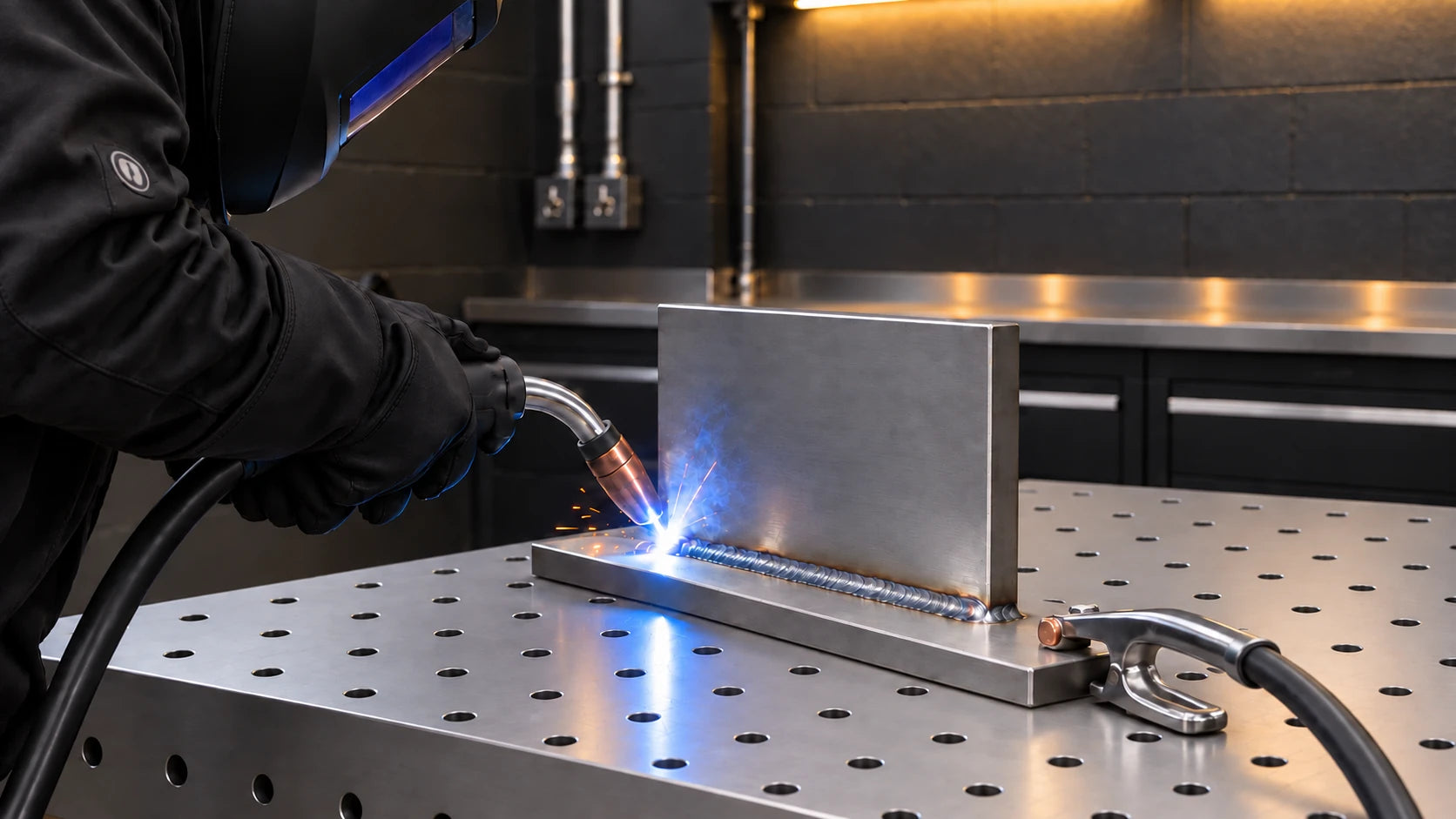
What is MIG welding?
Metal Inert Gas (MIG) welding is an arc welding process in which a solid wire (the filler metal) is continuously fed through the welding machine and into the weld pool that’s created by the arc to form a weld.
The process of MIG welding is semi-automatic, as the machine does all the wire feeding for you. This is why MIG welding is considered one of the easiest types of welding to learn and a great place to start for beginners.
Machine Setup
- Gas vs gasless
- Rollers
- Torch
- Wire spool
- Voltage/wire speed setup
1. Gas vs Gasless
Self-shielded flux-cored arc welding (FCAW-S) uses wire that supplies its own shielding; it is often sold as gasless MIG. Gas-shielded flux-cored wire (FCAW-G) is different and requires external gas.
| Pros of Gas | Pros of Gasless |
| Less spatter | Lighter & more portable |
| Less fumes | Lower cost setup |
| Welding quality | Outdoor use |
| Better performance on thinner material |
Select shielding gas for the wire, material and transfer mode. An argon/CO₂ mix such as 75/25 is common for mild-steel short-circuit MIG. Stainless steel needs an appropriate stainless-wire gas, such as a specified low-CO₂ argon blend or helium-based tri-mix; do not apply the mild-steel recommendation universally. Argon is commonly used for aluminium. Follow the wire and machine recommendations.
Use a compatible regulator and flowmeter; supplied accessories vary by machine package.
Choose gas flow from the wire and equipment guidance and check it while gas is flowing. There is no single flow rate for all MIG welding.
Protect the weld from draughts. Increasing flow alone may not restore shielding and can create turbulence.
For ordinary solid-wire MIG, the electrode is commonly positive and work return negative. Confirm the actual wire and mode before connecting leads; some machines switch polarity internally.
Set polarity from the wire classification and machine instructions. Solid-wire MIG commonly uses DCEP, while self-shielded wires may require DCEN or DCEP; not every machine supports every wire.
Connect the work-return lead as the selected polarity requires. This is the welding-current return, not the equipment's protective earth.
2. Rollers
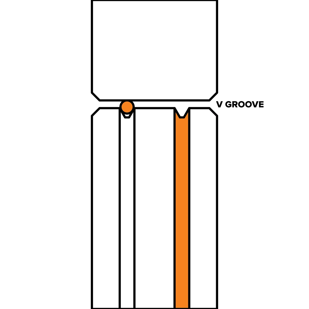
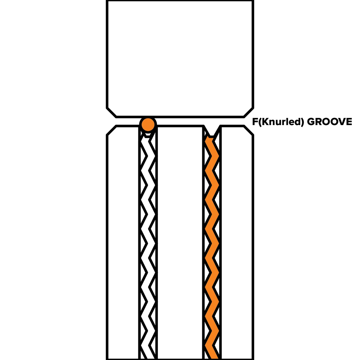
| Mild & Stainless Steel | Gasless Steel | Aluminium |
| V Groove | F or K Groove | U Groove |
 |
 |
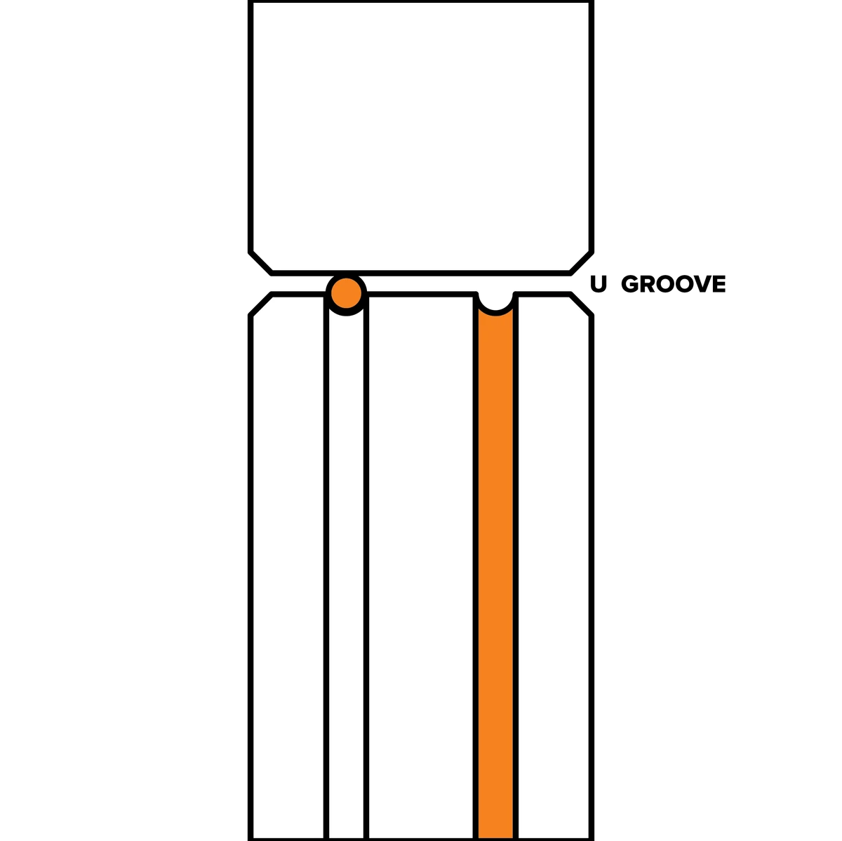 |
Fit the correct groove and roller type for the wire, following the feeder's markings and manual. Rollers and marking conventions vary.
3. Torch
Identify the machine's torch connection before fitting a torch. Euro connections are common, not universal.
3 types of MIG torches
- Binzel style
- Tweco style
- Bernard style
The main difference between these three torch types is that they were initially made by different manufacturers. Though the consumables for each look the same, you have to match your consumable type to the torch type; otherwise, they won’t fit.
Check the actual torch model and compatible consumables rather than assuming every supplied torch uses the same design.
Liners
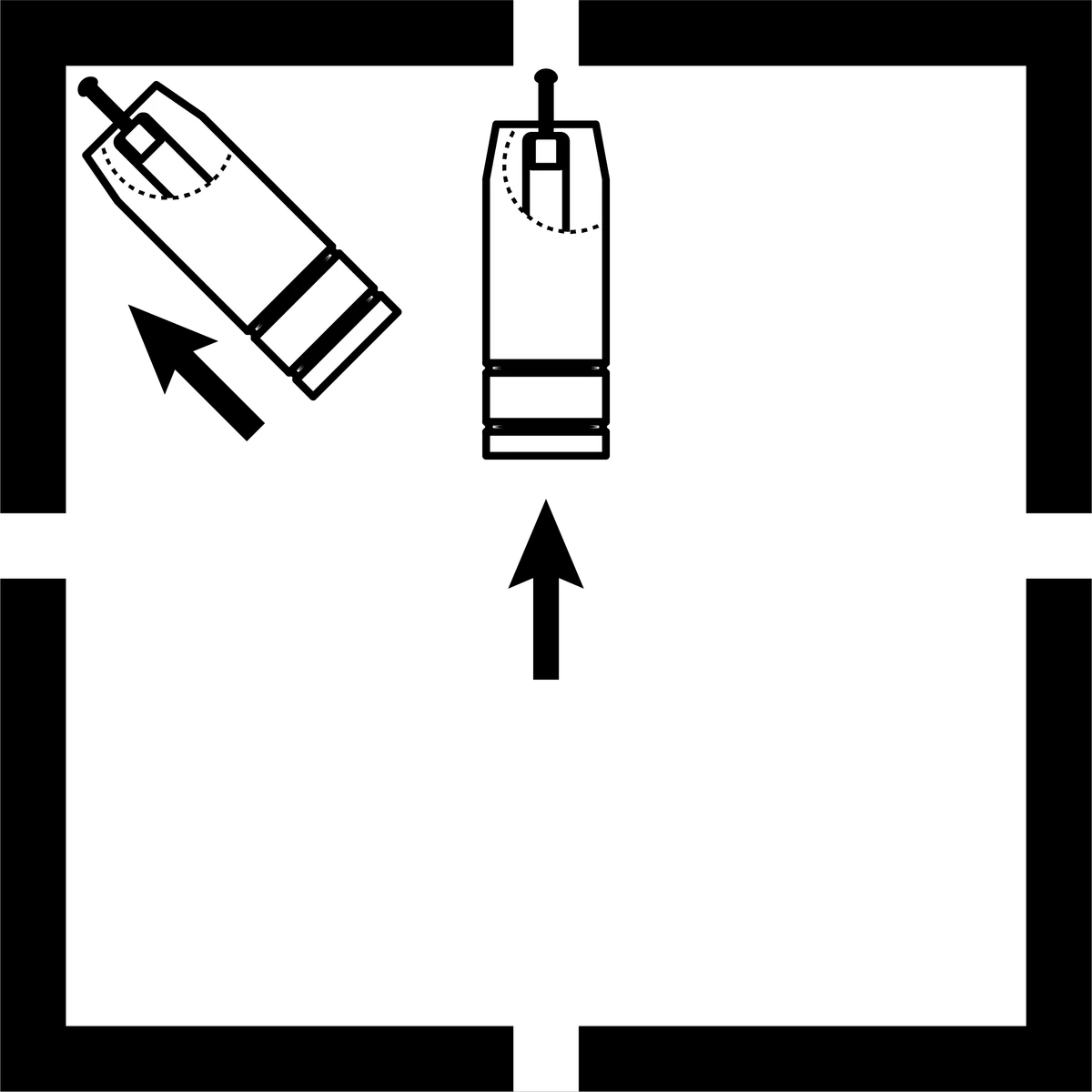
A liner guides your wire inside the torch lead, and this liner ensures the wire makes it out of the torch tip. You may need to change your liner before you feed your wire through, as these liners – much like the rollers – will only fit specific sizes.
Choose the liner for both wire material and its supported diameter range. A liner may cover more than one wire size.
Before changing a liner, isolate the machine and follow the torch manufacturer's removal and fitting procedure. The following sequence is an overview, not a universal trimming specification.
- Remove MIG torch front end parts.
- Remove the liner retaining nut.
- Carefully pull out and completely remove the existing liner. Ensure MIG torch is completely unravelled until setup is complete.
- Carefully feed in the new liner down the torch lead all the way to exit the torch neck.
- Fit the retaining hardware in the order and to the adjustment specified for the torch.
- Measure the required liner projection from the torch manual before cutting.
- Complete retention and front-end assembly as the manual specifies, checking that the liner is neither short nor compressed.
- Trim and secure the replacement to the dimensions and assembly order in the torch manual; an incorrect length can obstruct feeding or leave an unsupported gap.

When you’re changing your liner, it’s best to keep the torch entirely straight and go slowly, as you don’t want to kink the liner itself.
There are separate liners for steel wires and aluminium wires. If you’re going to use a standard MIG torch for an aluminium wire, you’ll need an aluminium specific liner (in the correct size).
Some polymer liner systems use a separate neck liner or guide. Fit one only where the torch manufacturer specifies it.
When you’re welding, try to keep the torch hose as loosely looped (or straight) as possible because it will minimise the chance of kinking the wire inside.
Spool Gun

As well as your standard MIG torches, you can also get an aluminium specific torch, called a ‘spool gun’. Spool guns are set up slightly differently than the MIG torches, as the wire spool is not connected in the machine but in the gun itself.
Select a spool size and adaptor supported by the feeder; not every machine accepts a 1 kg spool.
Keep hold of the free wire end while installing the spool and avoid kinks or crossed turns.
This is where your spool gun comes in. Because the wire is loaded into the gun (and then fed through the engine on the gun the same way the wire is fed through a machine’s roller mechanism), it has less distance to travel and less chance to kink.
Choose the wire classification, diameter and gas for the identified material and procedure.
If a synergic programme is used, select the matching wire and gas combination; it does not identify them automatically on every machine.
For a water-cooled torch, connect the specified coolant supply and return and verify cooler operation before welding; use the connection labels and manual.
4. Wire Spool
Before you begin, it’s essential that the filler metal you purchase matches the metal you plan to weld (your parent metal). Thanks to chemical compounds, mismatched metals won’t weld together properly unless you are using a filler metal capable of doing this, and the weld will be terrible quality.
The wire spool is like a loaded spring, so when you first undo the wire, don’t place it straight down onto a table or other surface as it will unravel, and you’ll have to clip off everything that has unwound.
If wire unwinds, inspect for kinks, contamination and crossed turns before reuse. Do not feed damaged wire into the torch.
Install the supported spool and adaptor, engage any locating feature and secure the retainer as described for the feeder. Set the brake separately where required.
You’ll need to feed the first part of the wire into the inlet guide, over the roller and into the beginning of the guide tube before you let go of it to stop it from unravelling.
Use the prescribed inching or threading mode. Keep the torch directed away from people and hands clear; on some machines the welding output can be live when the trigger is pressed.
With output isolated, remove the nozzle and tip if the threading procedure requires it. Nozzles may be threaded or slip-fit; use the method for the actual torch.
Set drive pressure using the feeder manufacturer's procedure, keeping hands away from the wire exit and moving rollers.
Where the manual specifies a blocked-wire test against wood, use that method with the prescribed setup. Do not grip feeding wire between your fingers.
Use only enough pressure for reliable feeding. Excess pressure can deform wire or worsen a birdnest when the path is obstructed.
Trim wire to the extension specified for the wire and transfer mode. Adjust burnback only as described for the machine.

5. Voltage and Wire Speed
Use the setup information for the exact machine, wire, gas and joint. Chart coverage and included accessories vary between models.

Metal Preparation
Unfortunately, MIG isn’t as forgiving as stick welding, so you’ll need to either wire brush or grind your workpiece so that it’s clean. Otherwise, you won’t get a quality weld.
Secure the workpiece before cleaning it. Use the grinder with its specified guard, handles, grip and suitable abrasive, together with the required eye and face protection.
Starting Your Weld
Now that your machine and workpiece are set up, you’re ready for the next step: starting the weld. With the voltage and wire speed set, the rest of the welding is up to you.
There are three main factors to consider when doing a weld:
- Work angle
- Travel angle & distance
- Travel speed
This is true regardless of whether you are TIG, MIG or stick welding.
1. Work Angle
Your work angle is your torch in relation to the angle of the joint. There are a few different joint types, and several positions in these joints can be found.
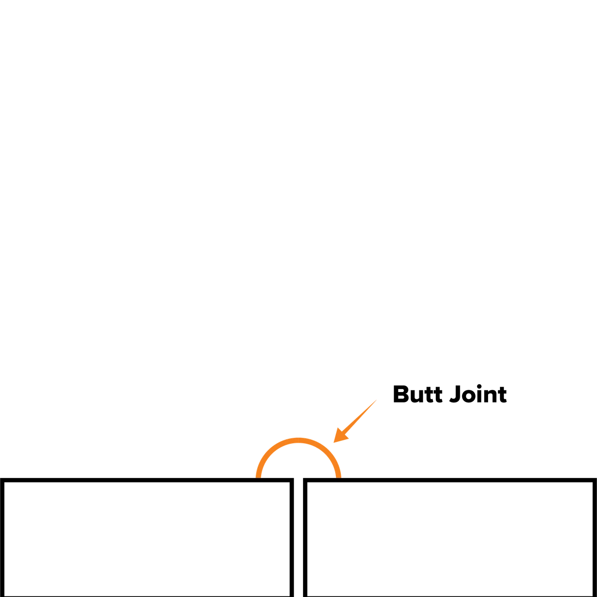
| T-joint / Fillet Joint | Butt Joint | Lap Joint |
| 90° joint angle | 180° joint angle | 90° joint angle |
| 45° work angle | 90° work angle | 60°/70° work angle |
 |
 |
 |
(These angles do not include your travel angle, which we’ll talk about next.)
Positions
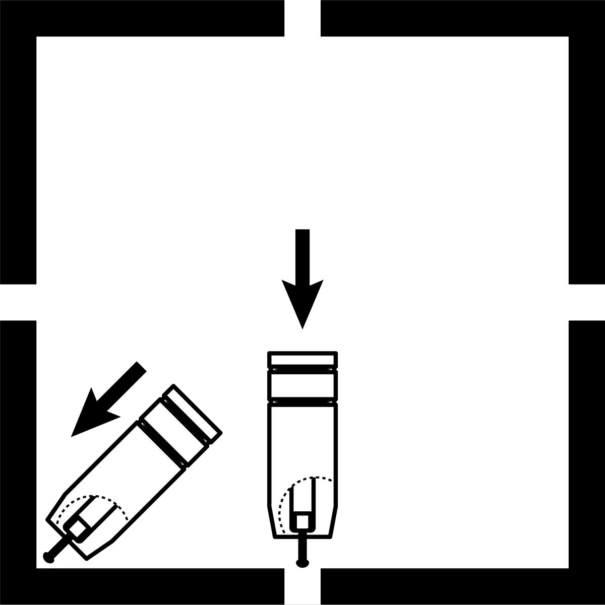
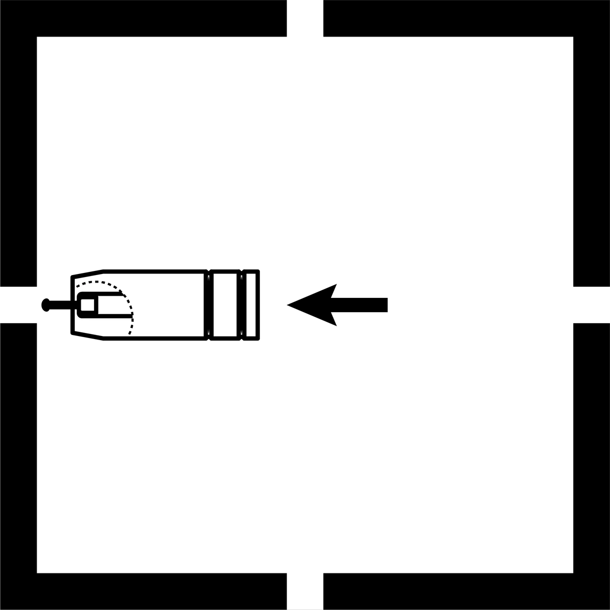
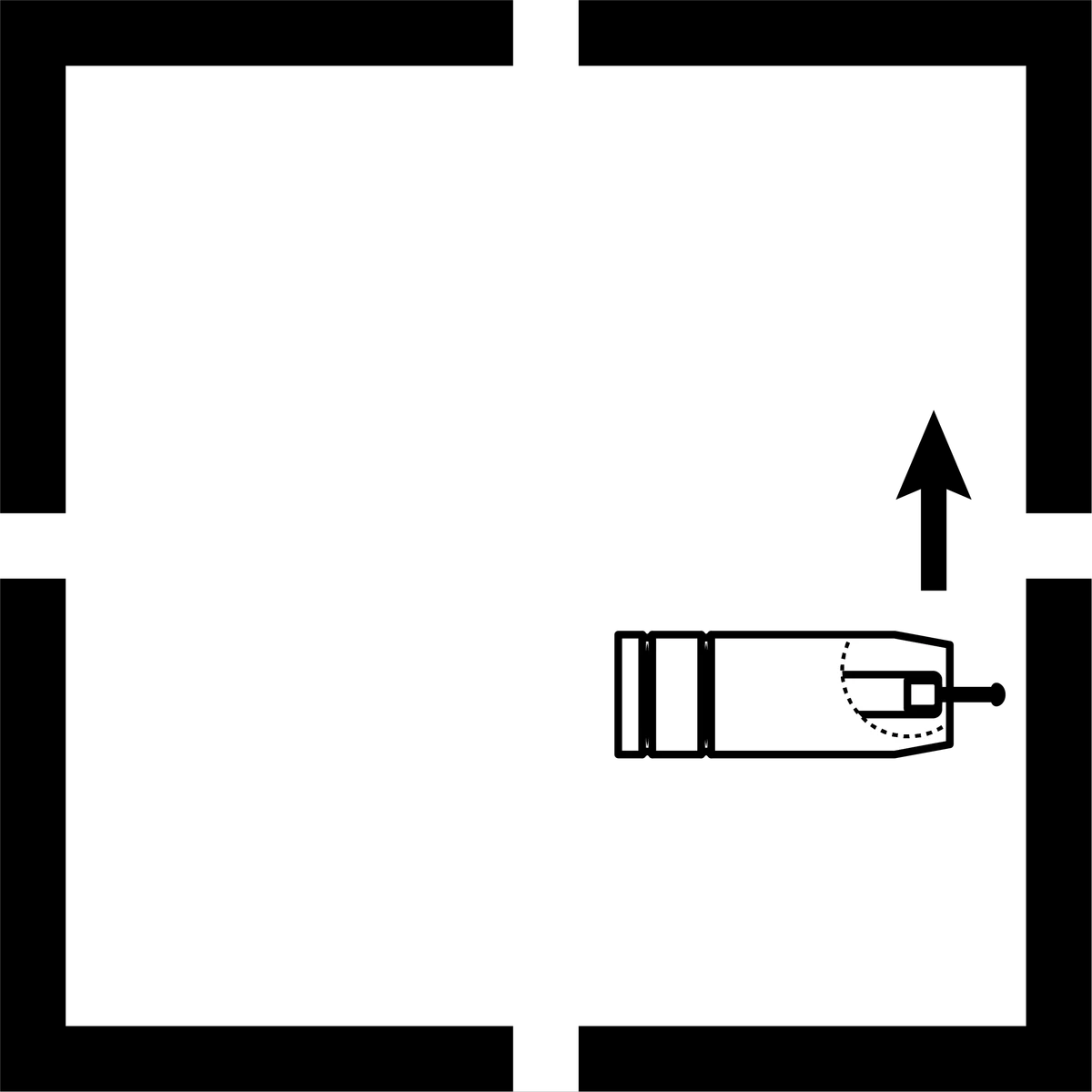
| Flat (butt & fillet) | Horizontal | Vertical | Overhead (butt & fillet) |
 |
 |
 |
 |
For vertical work, use a procedure and transfer mode suited to the direction and joint. Travel speed is not simply increased for every vertical weld.
2. Travel Angle & Distance
When MIG welding, you can travel at a pushing or a pulling angle, though it does depend on which wire is in the machine.
Solid-wire MIG can use a push or drag technique depending on the application; aluminium MIG commonly uses a push angle. Follow the procedure rather than a gas-equals-push rule.
Flux-cored wires may be self-shielded or gas-shielded. Use the wire maker's recommended travel angle, polarity and extension.
Use the procedure's travel angle; a small angle is common for general work, but 10–15° is not a requirement for every joint and transfer mode.

For example, say you’re welding in a fillet joint (a corner join) with a standard steel wire. Your torch will be angled into it at a 45° angle, and then you’ll angle slightly to the side (in a push direction) so that your gas can cover the weld pool and in front of the weld as you go.
Maintain the specified contact-tip-to-work distance and electrode extension; 10 mm is not universal across wires and transfer modes.

Longer electrode extension changes resistive heating and the current/arc relationship, especially with conventional constant-voltage MIG. Excessive extension can also reduce shielding and control.
3. Travel Speed
Travel speed is how fast you are moving the torch along the weld. This is separate from the wire speed, but the two do impact each other.
An oversized or convex bead can indicate incorrect settings or travel, but profile alone does not diagnose fusion.
Grinding a bead flat does not repair lack of fusion. Assess the defect and use a suitable repair procedure if it is unacceptable.
You want to move at a speed that corresponds with your settings. Keep your travel speed consistent across the entire weld for the best quality result.

Making the Weld
Place your cleaned workpiece in front of you in a way that when you begin welding, your hands can move freely and steadily all the way along the joint. It’s a good idea to have something to steady your hands against as they go along the weld so that you can maintain your angle and distance.
Make a clean, secure work-return connection. A poor connection can destabilise the arc and overheat the contact.
If you’re making a fillet join, you can use a magnetic welding clamp to hold your two pieces of metal together. Aluminium isn’t magnetic, however, so a manual clamp will be needed.
The kind of wire you are using will determine the technique required when welding.
Push Technique (Gas-shielded Wires)
The wire is located at the leading edge of the weld pool and pushed towards the un-melted work surface. This technique offers a better view of the weld joint and direction of the wire into the weld joint.
The push technique directs the heat away from the weld puddle, allowing faster travel speeds and providing a flatter weld profile with light penetration – useful for welding thin materials. The welds are wider and flatter, allowing for minimal clean up/grinding time.
Pull Technique (Gasless Wires)
The gun and wire are pulled away from the weld bead. The arc and heat are concentrated on the weld pool. The base metal receives more heat, deeper melting, more penetration and the weld profile is higher with more build-up

Start with your tacks. Remember to flip your welding helmet down before you ignite your arc. Tacks are used to fuse the metals together at the edges, so you don’t have to hold them together while you’re trying to weld.
Line your torch tip and wire up with where you want to make your tacks (usually on the edges of the piece) and press the trigger of your torch. You’ll need to hold it continuously to maintain the arc. Hold it for a second or two until a small weld has formed, and then let go.
Tacks must hold the required fit-up and be acceptable for incorporation into the final weld where intended. Their size is not defined by a fixed number of seconds.
MIG welding itself is relatively easy once you’ve got the hang of your angles and speed; all you need to do is press the trigger and start pushing or pulling your weld along the joint.
Arc sound varies with transfer mode. Short-circuit MIG may crackle, while spray and pulse sound different; inspect the weld rather than using one sound as proof of quality.
If you’re trying to weld thicker pieces of metal together, adjust your volts and wire speed accordingly.
Once you’ve run your weld along the joint, you’re done. You’ve made your first weld!
Because MIG welds do make spatter, and if you use a gasless wire with a flux core, some post weld work needs to be done. If you’ve used a flux wire, you’ll need to use a chipping hammer to take off the slag that formed its protective layer over the top of the weld.
If there is spatter everywhere, you can grind this off for a cleaner looking weld or, alternatively, you can use an anti-spatter spray before welding. If the weld is just for practice, it doesn’t matter how good it looks.
Just remember that dry runs and scrap metal are your friends. Practice running your welding torch across a piece of metal, maintaining your travel angle, distance and speed until you’re confident that you can keep all three of them consistent.
Once you’re happy with your performance on a dry run, try it again on some scrap metal before you move on to the piece you’re planning on welding. If you don’t get it the first attempt, that’s fine; no one’s expecting you to be a welding expert on your first go. Practice makes perfect.
Article written by UNIMIG Australia - published March 2, 2021 titled "The Ultimate Guide to MIG Welding"
Sources for revised guidance
Reference diagrams: UNIMIG. Original source attribution is retained.
Related guides
TroubleshootingMIG Wire Feeding Problems: A Step-by-Step Troubleshooting Guide Process guideMIG Metal Transfer Modes: Short Circuit, Globular, Spray and Pulse Maintenance guideHow to Change a MIG Torch Liner: Steel and Teflon LinersGet the right MIG consumables together.
Have your machine and torch models, wire type and diameter ready.
Ask us about thisTechnical sources and scope
Reviewed 22 September 2026. Manufacturer examples apply to the named equipment; use the current manual for your exact model and the required welding procedure.
- Miller — feeder operating manual and drive-pressure procedure
- ABICOR BINZEL — PP torch operating and liner-fitting manual
- Miller — stainless MIG setup and gas selection
- Miller — pulsed MIG welding
- SafeWork NSW — Welding processes code of practice (2022)
Feeding and consumable instructions are scoped to the actual equipment; unsafe finger-grip testing was removed.


