
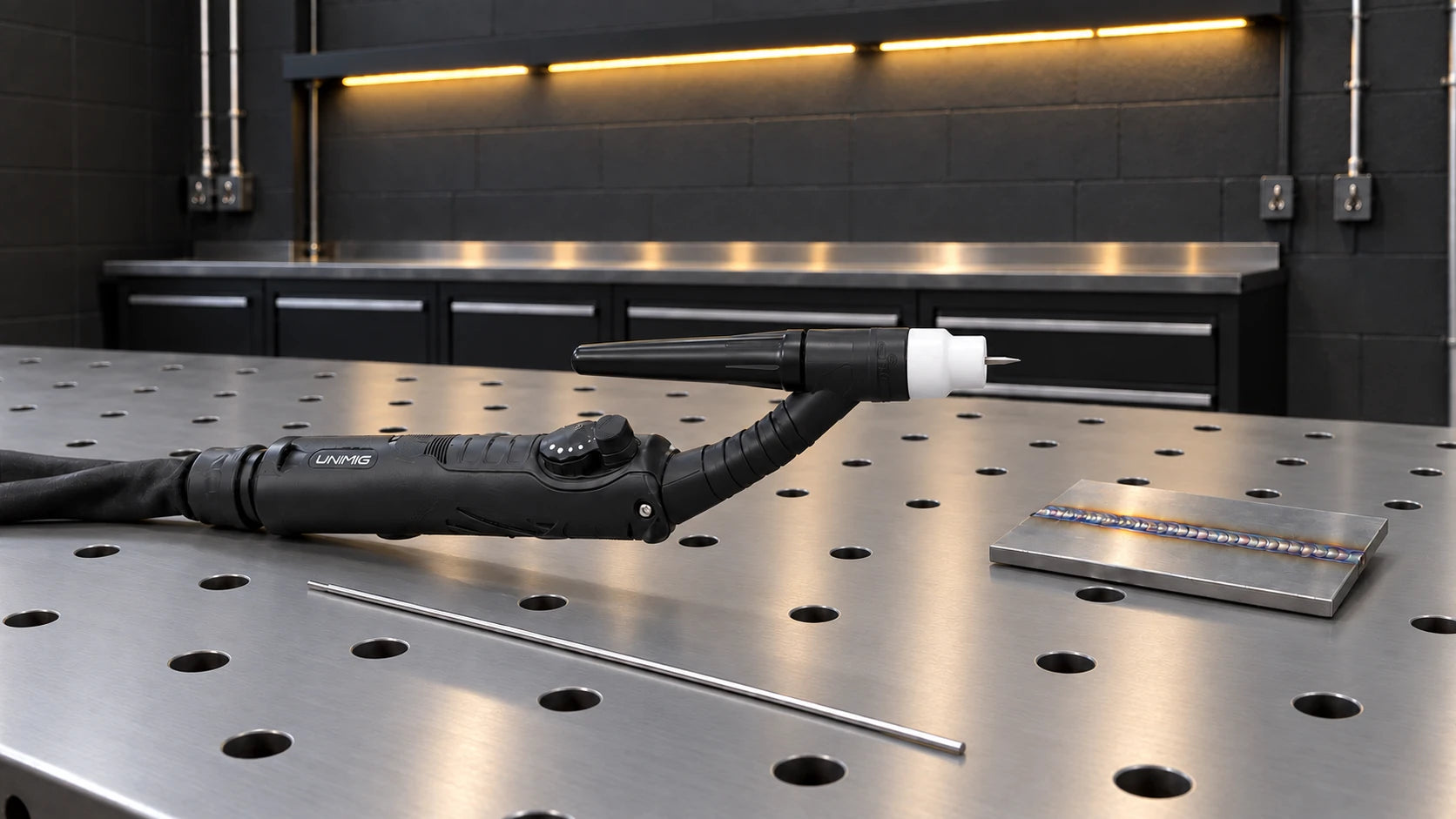
What is TIG welding?
Tungsten Inert Gas (TIG) welding is the process in which an arc is formed between a tungsten electrode and the workpiece to join the metals together. A filler rod is often fed into the weld pool by the operator to create a weld. A shielding gas is also required to protect the weld from atmospheric contaminants that could cause weld defects such as porosity.
TIG welding is considered the most challenging type of welding to learn as there is a lot more room for human error.
Tungsten Choice
There are several different types of tungsten, each with their own unique properties and limitations.
- Pure tungsten (Green tipped)
- Thoriated 2% (Red tipped)
- Ceriated 2% (Grey tipped)
- Lanthanated 1.5% (Gold tipped)
- Zirconiated 0.8% (White tipped)
- Rare Earth (Purple tipped)
| Electrode | Application notes |
|---|---|
| Lanthanated | Common AC/DC option on suitable inverters; identify the actual oxide content and current range. |
| Ceriated | Often useful at lower current; use the maker's AC/DC guidance. |
| Zirconiated | Principally an AC choice; not automatically best for every inverter. |
| Thoriated | Traditionally used for DC; not universally excluded from AC. Thorium requires appropriate handling and dust controls. |
| Mixed oxide / rare earth | Composition varies by product. Colour alone does not establish equivalence. |
Select diameter and tip preparation for current, waveform and polarity. This replaces an unsupported dot-rating chart.
The tungsten that best fits your job will mainly depend on your parent metal and application, as not every tungsten will work with every metal. The thickness of your workpiece will also be a factor in which tungsten you’ll need.
Choose tungsten diameter for welding current, polarity, waveform and the electrode manufacturer's range, rather than material thickness alone.
Lanthanated electrodes are a common option for modern AC/DC inverters. Ceriated electrodes can suit lower-current work; check the machine and electrode guidance for the intended application.
Tungsten Preparation
Now that you’ve selected the tungsten that fits your job, the next step is to prepare it for the weld.
Before you start, make sure that you are prepping the non-coloured end of your tungsten. The tungstens are colour coded because they are almost identical in appearance. You don’t want to grind off your coloured end, as you won’t know what it is later.

There are a few different ways to prepare your tungsten, and different shapes will give different results on different applications.

Some conventional AC setups use a rounded tip. Modern inverter TIG commonly uses a prepared point or truncated point; follow the power-source and electrode instructions.
Do not use a generic DCEP balling procedure. Excessive positive-electrode current can overheat the tungsten and torch.
For a pointed or truncated electrode, use a suitable tungsten grinder with controlled dust collection.
If you use a bench grinder, it needs to be dedicated to tungsten preparation, as you can contaminate your tungsten with anything that’s leftover on the grinder.
Grind lengthwise with a dedicated wheel. Select the point angle and tip flat for the current and procedure; 30° is not a universal preparation rule.
Circumferential grinding marks can encourage arc wandering. Keep the tip concentric and avoid contamination from a wheel used on other metals.
A truncated tip follows the same preparation as a pointed tip but with the added step of grinding the end, so you get a flat top. This shape works well for both AC and DC applications.
Use the same preparation consistently on practice pieces, changing it only within the electrode and machine guidance.
Metal Preparation
When you’re TIG welding, your workpiece must be clean. If the metals you want to join are rusted, have paint on them, are oily or otherwise coated in some way, you’ll need to grind the metal until it’s squeaky clean. If you leave anything on your workpiece, your weld could be contaminated, and it won’t be a quality weld.
For aluminium, remove oil with a suitable cleaner, let it dry, then remove oxide with a dedicated stainless-steel brush or suitable aluminium-preparation abrasive. Grinding is not inherently prohibited, but avoid smearing or embedding contamination.
Machine Setup
- Gas
- Torch
- Machine Settings
1. Gas
Argon is a common TIG shielding gas for many materials. Specialised mixtures also exist; select the gas for the material and procedure rather than assuming one bottle suits every job.
Use a regulator and flowmeter compatible with the gas cylinder and TIG application. Check the package contents rather than assuming one is supplied with every machine.
Read the regulator and flowmeter according to their design. A pressure gauge measures pressure; the calibrated flow indication shows gas delivery while flowing.
Set flow with gas actually flowing, using guidance for the cup, torch and procedure. Cup size, electrode extension and draughts affect coverage; one flow rate cannot suit every setup.
2. Torch Setup
Scratch, lift and high-frequency starting are power-source functions. Torch valves, switches and remote controls must match the machine; a torch alone does not add an arc-start mode.
3 types of TIG
- Scratch start: The electrode is briefly scratched on the work to initiate the arc; this can contaminate the tungsten or weld.
- Lift start: The machine controls current while the electrode touches the work, then establishes the arc as it is lifted.
- High-frequency start: A compatible power source starts the arc without touching the electrode to the work, using its specified trigger or remote.
Use the compatible torch and trigger or remote specified for the selected start mode. A manual gas-valve torch may require separate control of gas flow.
Some AC/DC machines support lift start on AC as well as DC. Check the actual machine; AC does not universally require an HF-labelled torch.
A compatible torch potentiometer or foot control can adjust current when the power source supports that remote function.
Rigid and flexible torch heads suit different access needs. Check the bend limits and supplied torch for the exact model and package.
Standard torch sizes
Common torch families include 9/20 and 17/18/26, with compatible consumable families in many standard designs. Confirm part numbers, insulators and threads before mixing parts.
A smaller torch can improve access, but its current rating depends on its construction, cooling, shielding gas and stated duty cycle.
Choose the torch by its published rating at the required duty cycle, not its size alone.
Polarity
For typical DC TIG on steel and stainless steel, use DC electrode negative (DCEN): torch to negative and work-return lead to positive, as specified in the machine manual. Aluminium TIG commonly uses AC, so “TIG is always negative polarity” is not a valid description of the welding current. Follow the manufacturer’s connection instructions for each mode.
With the equipment isolated, connect the torch, control lead and gas fittings exactly as shown in the machine and torch manuals.
A water-cooled torch needs the specified coolant circuit, flow and cooler operation. Identify connections from the manual rather than relying only on hose colour.
The correct polarity setup is available in our User Manual that comes with each machine (and is available online), so don’t stress if you forget.
Building your TIG torch
To set up your torch you should have:
- Your chosen tungsten
- Collet
- Collet body
- Back cap
- Ceramic cup (gas shroud)

Select the collet and body by their marked electrode size and torch compatibility. Nominal size is a selection label, not an instruction to measure or drill the bore.
Your ceramic cup is marked with a number indicating how large the cup’s opening is, which will determine how much gas coverage you will get to protect the weld. They also come in a variety of materials, such as Quartz (Glass).
Clear cups can improve visibility. They need the specific diffuser or gas-lens assembly and insulator designed for that cup; clear material alone does not provide wider gas coverage.
Gas lenses are an optional accessory on TIG torches which replace the collet body inside the torch. They’re especially useful when welding inside corners or in tight spaces because you can stick the tungsten out further thanks to the extra gas coverage.
Standard lens vs Gas lens
Standard nozzles release a broad plume of shielding gas over your weld. In comparison, a gas lens improves shielding gas coverage by distributing gas around the tungsten more efficiently with less turbulence. You can also have the tungsten stick out further with a gas lens, giving you better manoeuvrability and visibility of the weld pool. This is great for when you need to weld in tight spaces.
If you are using a gas lens, you’ll need a gas lens ceramic cup, as a standard one won’t fit. The below steps don’t change much if you’re using a gas lens.

Torch Assembly
- Fit the collet into the collet body.
- Fit the tungsten through the collet and collet body.
- Screw the collet body into the torch head.
- Screw the back cap onto the torch head. Don’t fully tighten just yet.
- Screw in the ceramic cup onto the front of the torch.
- Finally, adjust the tungsten to your desired length, then fully tighten the back cap.

Set electrode extension for the cup, gas distribution, joint access and procedure. A gas lens may permit more extension, but shielding must still cover the hot electrode and pool.
It’s okay if your tungsten is sticking out too far after you’ve screwed the back cap on; just unscrew it until the tungsten becomes loose, slide the tungsten back until it’s the correct length and then re-screw the back cap until the tungsten is snug again.
Now your torch is complete and ready for use.
3. Machine Settings
The illustrated RAZOR 200 AC/DC panel is an older model example. The terms below explain the functions; button sequences, ranges and remote-control behaviour must come from your exact model manual.
Starting on the far left is a column of five, with the following options:
- AC
- AC PULSE
- DC
- DC PULSE
- MMA

MMA is stick mode. It is available only on machines that list that capability; a TIG output is not automatically a stick output.
The other four options are what we use to TIG weld with. AC currents are used when working with aluminium, and DC is used for steel and stainless steel.
Pulse alternates between peak and background current. Heat input and fusion depend on both currents, their time proportions and travel speed; pulsing does not inherently mean less penetration.
Moving slightly to the right is a column of three options:
- 2T
- 4T
- SPOT

These stand for two touch, four touch and spot.
In a typical 2T trigger sequence, hold the switch to weld and release it to start the finish sequence. Check the model's remote and downslope behaviour.
A typical 4T sequence uses press-and-release actions to start, latch and finish welding. The exact start and end-current stages vary by model.
Spot mode times the arc where that function is supported. Foot-pedal operation and the required trigger mode vary by machine; use the specified remote settings.
Next up is the pyramid steps. These are the parameter settings and are the ones you’ll need to change when swapping between welds. In order from left to right, they are:

- Pre-gas: this is the gas that shields the tungsten and area you are about to start welding from the atmosphere. Use the knob to select how long you would like your pre-gas to flow before the arc ignites.
- Start amps: these allow for a lower or higher amp start, depending on your material. If you have a thicker piece of metal, you’ll want to start on higher amps than if you’re welding a thinner piece.
- Up slope: your up slope will dictate the amount of time (in seconds) it will take to reach your peak amps from your start amps. The more time you input, the longer it will take for the amps to increase. A longer up slope is recommended for thinner metals to prevent burning straight through.
- Peak amps: these are the amps you will do your welding on until you have finished the joint. If you are set to AC/DC pulse, this will be the high part of your amp cycle.
- Base amps are the lower current during a pulse cycle. Compare peak current, background current and peak-time percentage together; increasing the peak-to-base gap does not by itself make a weld cooler.
- Down slope: your down slope will dictate the time (in seconds) between your peak amps and your finish amps. This will taper the arc to prevent crater holes and cracks in the weld.
- Finish amps: this is the final amp level that the machine will reach before your arc extinguishes. If you turn this up, it will be a hotter finish, suited to thicker materials. Turning it down will provide a cooler finish suited for thinner materials.
- Post-flow shields the hot tungsten and weld after the arc stops. It does not fill a crater; use the appropriate finish current, downslope and filler technique for that.
- AC balance changes the proportion of electrode-negative and electrode-positive time. Machines may display EN%, EP% or a relative scale, so confirm the display convention before adjusting it.
- AC frequency is the number of complete AC cycles per second. It affects arc concentration and feel, but the resulting bead also depends on current, balance and travel.
- Pulse frequency sets how often peak and background current repeat; pulse percentage sets time at the designated level. Check what the machine's percentage refers to and trial the combined settings.
- Arc force and spot time are separate functions sharing a control on some panels. Arc force affects stick-welding response at short arc length; spot time controls the duration of a timed weld.
On the right side of the adjustable knob are three lights:

These lights won’t always be illuminated, and you definitely don’t want the parameter warning light to be on.
Remote: Connect the approved current control and select the mode described in the model manual. Do not assume holding the torch switch for five seconds or selecting 2T is the correct setup on every machine.
Tungsten Electrode mm: input your tungsten width here. The machine will only provide a limited number of options, as there are only so many tungsten sizes. You can navigate to this setting with the control knob.
Parameter warning: Read the model manual for the meaning of an indicator. A warning is not a substitute for selecting the correct electrode and checking the actual arc.
Mixed Arc AC/DC Welding
Mixed AC/DC welding is the combination of TIG AC and TIG DC- in one weld. There are quite a few benefits from this type of weld, including higher welding speeds and penetration, and a faster weld puddle on cold workpieces. Mixed AC/DC also means that you can weld on thicker materials.
Mixed AC/DC modes alternate AC and DCEN periods. Available ranges and suitable settings are specific to the machine and procedure; there is no universal 50% DC limit.
Check current model specifications for mixed AC/DC capability. It is not exclusive to the older RAZOR 320 example.
Filler Metals
The second part of TIG welding is your filler rod – the metal you’ll be using to feed into the weld pool. You need to match your filler rod metal to your parent metal, as dissimilar metals only weld together if you have the right filler. These rods usually come in 50cm or 1m lengths, so it’s a good idea to cut them down to a comfortable size as it’ll make it easier to feed.
There are a few different classifications for each type of filler rod available.
Steel Rods:
- For mild steel, select filler from the identified base metal and required properties. ER70S-2 is one common TIG option, not the best filler for every steel.
- ER70S-4
- ER70S-6
Stainless Steel Rods:
- For stainless steel, match the filler to the base-metal grades, service environment and welding procedure.
- 316L filler is commonly used with 316L base metal; it is not a universal stainless filler.
- Dissimilar stainless joints and corrosion-critical work need a specific filler recommendation.
The ‘L’ refers to the extra low levels of carbon in the rods, which helps prevent corrosion in the welds.
Aluminium Rods:
- For aluminium, identify the alloy before choosing filler. 4043 and 5356 are common choices with different compatibility and service limits.
- Use the filler manufacturer's alloy-selection chart; do not choose solely from the alloy series number or desired bead appearance.
Filler diameter depends on joint size, required deposition and current. It does not have to equal the tungsten diameter.
Starting Your Weld
Once your equipment is all set up, you’re ready for the fun part: starting a weld.
Three main factors need to be considered when doing a weld:
- Work angle
- Travel angle & distance
- Travel speed
This is true regardless of whether you are TIG, MIG or stick welding.
1. Work Angle
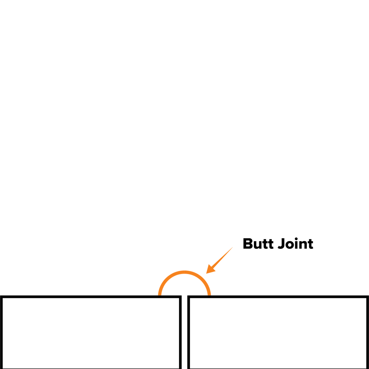
Your work angle is your torch position in relation to the angle of the joint. There are a few different joint types, and several positions these joints can be found.
| T-joint / Fillet Joint | Butt Joint | Lap Joint |
| 90° joint angle | 180° joint angle | 90° joint angle |
| 45° work angle | 90° work angle | 60°/70° work angle |
 |
 |
 |
(These angles do not include your travel angle, which we’ll talk about next.)
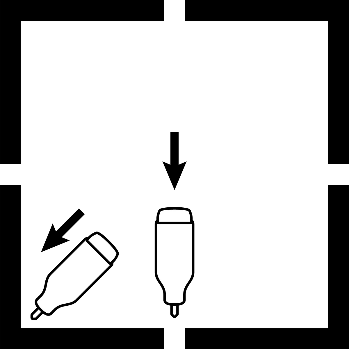
| Flat (butt & fillet) | Horizontal | Vertical | Overhead (butt & fillet) |
 |
 |
 |
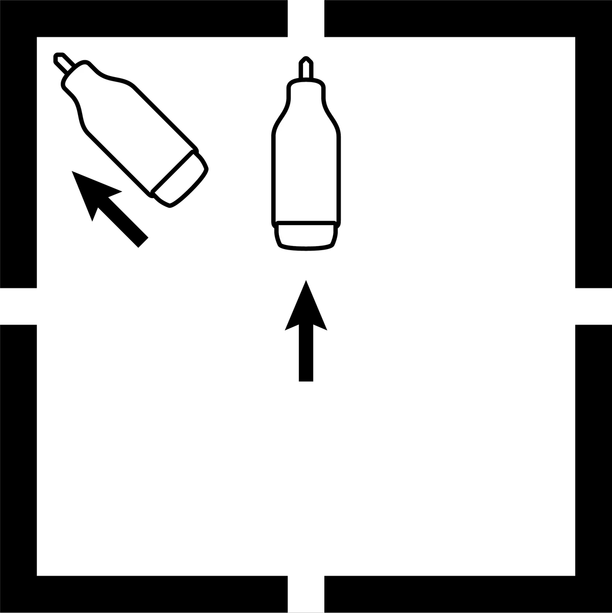 |
The main thing that your weld’s position will affect is whether or not you’ll be fighting against gravity as you go. While you’re learning, flat positions are best.
2. Travel Angle & Distance
A slight forward torch inclination is a common starting technique. Maintain shielding and access; pulling does not automatically prevent fusion or cause porosity.
For a basic equal-leg fillet, aim approximately between the two faces, with a slight forward travel inclination. Adjust for joint geometry, access and the welding procedure.
Feed filler into the leading edge of the pool at an angle that maintains shielding and avoids the tungsten.
Keep a short, controlled arc appropriate to the electrode and joint. A fixed 3 mm gap is not right for every TIG weld.
Excessive torch inclination or arc length can reduce control and shielding. Correct the setup rather than assuming any one symptom proves the cause.
If the tungsten touches the pool, stop and isolate the output before removing it. Let hot parts cool, remove the contaminated tip with suitable cutting equipment and regrind it; do not snap it.
Travel Speed
Travel speed is how fast you are moving the torch along the weld. The speed you travel affects how far the weld penetrates. Too fast, and it won’t go far enough, too slow, and you could burn a hole straight through. Your travel speed also dictates the weld’s conformity; if you’re speeding up or slowing down, then the weld won’t be even.
Maintain the travel and pool control required by the joint; evaluate the result against its specified weld size and quality.
Making the Weld

Place your cleaned workpiece in front of you in a way that when you begin welding, your hands can move freely and steadily, and you can comfortably complete the joint. It’s a good idea to have something to steady your hands against as they go along the weld so that you can maintain your angle and distance.
Attach the work-return clamp to clean metal with a reliable current path, preferably directly to the workpiece near the weld. It completes the welding circuit and is separate from protective earthing. Use fixtures suitable for the material and joint.
Start with your tacks. Remember to flip your welding helmet down before you ignite your arc. Tacks are used to fuse the metals together at the edges, so you don’t have to hold them together while you’re trying to weld. This is especially important when TIG welding as you don’t have any free hands.
Hold your torch in your dominant hand and your filler rod in your other hand. Press the button on your torch to start the arc (keeping pressure on it in 2T mode) until you see a wet pool forming. Dab a small bit of filler rod into this pool and then release your button. You’ve just made your first tack.
Place tacks to maintain the specified fit-up. Use filler where the alloy or procedure requires it; a tight joint alone does not make an autogenous tack suitable.
To make the weld, start the same way as you did to make the tack. Press the button (holding it down if you need to) until the metal begins to pool. Then dab the filler wire into the leading edge of the weld pool. You don’t want to touch it onto the tungsten in the middle of the arc. You are aiming to push the filler wire into your pool to make the best weld.
Add filler at a rate that maintains the intended weld size and pool control. There is no universal requirement to dip a length equal to the rod diameter.
At the end, complete the specified crater-fill or downslope sequence and hold the torch over the weld during post-flow.
Inspect the finished weld for the required profile and visible imperfections. A neat ripple pattern alone cannot establish fusion, penetration or acceptance.
Fusion Welding
TIG welding without added filler is called autogenous welding. It is used for suitable joints and materials when the procedure allows it; it is not inherently limited to weak practice welds. On scrap, it is also useful for learning puddle control. Joint fit-up, material and required weld properties determine whether filler is needed.
Back Purging
Back purging protects the root from atmospheric oxidation where the material and procedure require it. Carbide precipitation is a different metallurgical issue, not another name for exposure to air.
Heavy root oxidation or sugaring can compromise stainless weld quality. Assess it against the service and acceptance requirements; appearance alone does not establish the extent of damage.
Use a suitable gas arrangement with independently controlled torch and purge flows. One cylinder may serve both through approved equipment; an extra cylinder is not always necessary.
Use suitable purge dams or plugs arranged for the joint, heat and gas flow.
Provide a safe gas outlet so the joint is not pressurised. Purge gas also needs ventilation away from personnel.
Follow the procedure's purge flow, time and, where specified, oxygen limit. A smooth-looking root alone does not verify an adequate purge.
The best way to get better at something is to practice, practice, practice! You can make dry runs as many times as you need to feel comfortable with the motion before starting an actual weld.
If you’ve got some spare or scrap metal, you can practice making beads on the parent metal (make a weld pool, push it along the metal at a steady pace, repeat) without adding any filler metal (fusion) to practice the torch motion and to get a feel for how long it takes for the pool to form each time.
For stainless service work, do not reduce shielding to create decorative colours. Heat tint is oxidation and may require removal under the finishing specification.
Sources for revised guidance
Reference diagrams: UNIMIG. Original source attribution is retained.
Related guides
Consumables guideTIG Tungsten Selection: Types, Colour Codes and Applications Consumables guideTIG Collet Body vs Gas Lens: Differences and Selection Process guideHow to Weld Aluminium: MIG, TIG and TroubleshootingMatch the TIG setup to your material.
Tell us your machine, torch, material and the work you need to do.
Ask us about thisTechnical sources and scope
Reviewed 22 September 2026. Manufacturer examples apply to the named equipment; use the current manual for your exact model and the required welding procedure.
- Miller — TIG welding basics
- Miller — electrode preparation and TIG operating manual
- CK Worldwide — tungsten types and classifications
- Miller — TIG shielding gas and gas lenses
- Miller — operating manual with AC/DC Lift-Arc modes
- Miller — advanced aluminium MIG and TIG techniques
- TWI — heat tint and stainless weld oxidation
- SafeWork NSW — Welding processes code of practice (2022)
The legacy panel remains an illustration. Button sequences and settings are limited to the exact manual; filler and electrode selection remain application-specific.


