
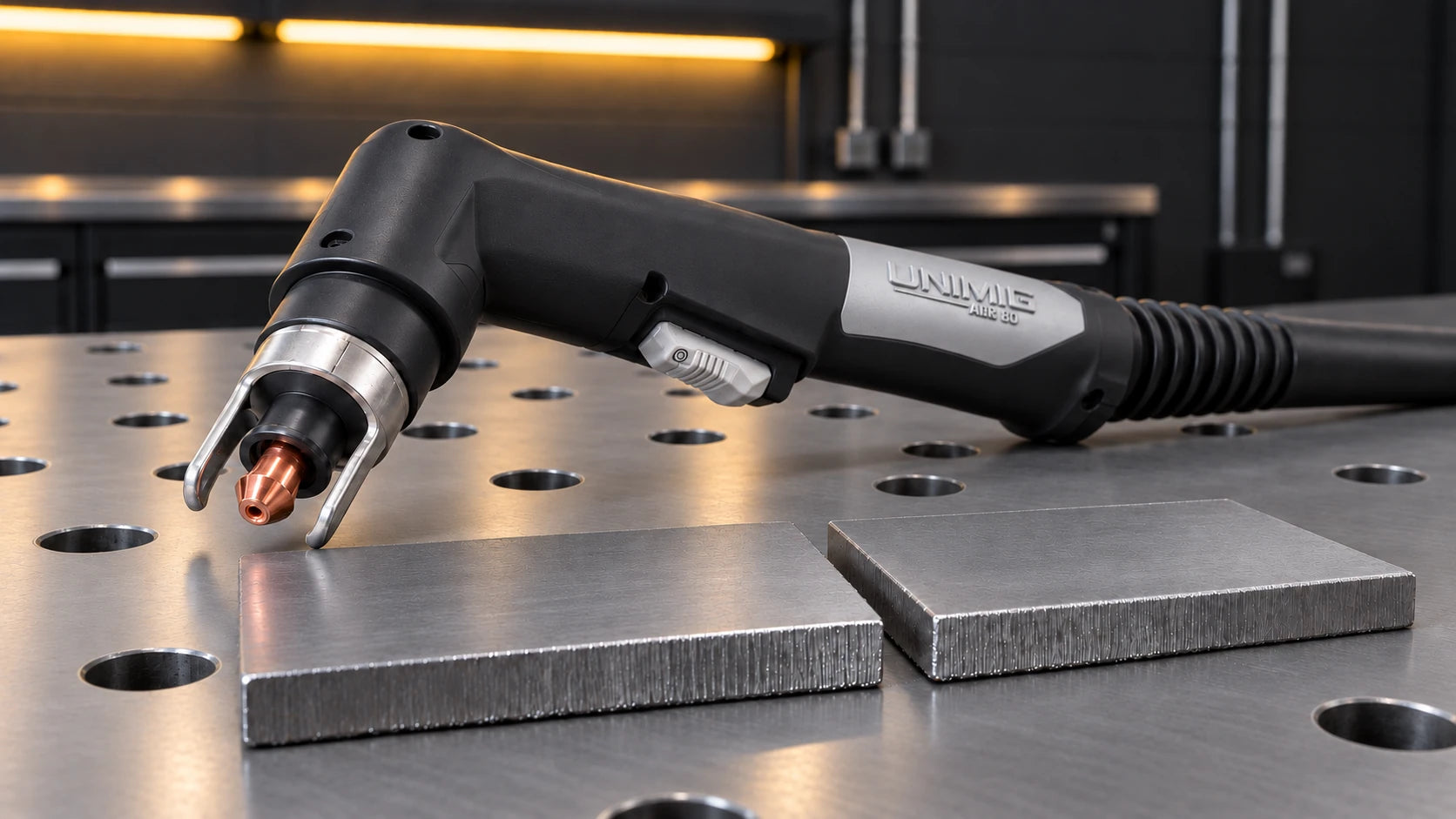
What is Plasma Cutting?
Electrical energy ionises the process gas. The constricted plasma arc melts the metal and the gas stream ejects it from the cut.
Plasma cutting (plasma arc cutting), therefore, is a melting process that uses plasma and an outside power source to create an electric arc between the electrode and the metal being cut to melt and eject it from the cut.

Unlike conventional oxyfuel cutting of carbon and low-alloy steel, plasma can cut other electrically conductive materials within the system's approved range.
Machine Setup
- Air/Gas
- Torch & Consumables
- Settings
1. Air/Gas
Many workshop air-plasma cutters use compressed air, including the examples in this guide. Plasma systems also exist that use other process gases. Use only the gas specified for your particular machine and application.
Check whether the exact machine has an integrated compressor or needs an external air supply. Use only the specified air or gas connections and equipment.
An external compressor adds equipment and power requirements. Select it by delivered airflow at the cutter’s specified operating pressure, not intake volume alone. Check sustained demand, hose losses and the air-quality requirements in the cutter manual.
If you’re looking for more portability, some machines come with built-in air compressors, like the RAZOR CUT 40 AIR Plasma Cutter. These machines will still need a power supply, however.
An air dryer or filter is essential for keeping contaminants like moisture and dust particles out of the machine’s air lines. Moisture in the pipes will come out in your torch and cause your consumables to burn up faster, resulting in bad cuts, which is something you’d like to avoid.
Depending on which model machine you have, your air dryer/filter can be found inside the machine or at the back of the machine.
3 types of filter
The original photograph is no longer available. The named equipment and surrounding information have been retained.
- Basic
- Roll
- In-line
Check filter condition and the air-quality requirements in the cutter manual.
Drain the compressor receiver and filters using their prescribed procedure; not every filter drains automatically.
Provide the filtration or drying needed for the actual air supply, including moisture and oil control.
A basic water trap does not necessarily deliver sufficiently dry, clean air by itself.
2. Torch & Consumables
Plasma cutting commonly uses an electrode-negative output. Connect only the approved torch and work lead as instructed; plug shape is not a substitute for checking the connection.
With power isolated, connect the specified torch and work lead to their designated sockets; do not assume the connectors make incorrect assembly impossible.
Attach the work-return clamp to the main workpiece with a sound current path, avoiding an offcut that will fall away. It is not protective earthing. Follow electrical precautions regardless of where the clamp is attached.
On a combined welding/cutting machine, select the correct process and lead arrangement before use.
Consumables
The attachments on your torch will make a significant difference to the type of cutting you can do with your machine.
Types of Shields
- Contact cutting
- Gouging
- Stand off cutting
Available cutting and gouging modes depend on the torch and consumables. Check the exact SC30 or SC80 parts list instead of assuming each supports every shield type.
Use drag or stand-off cutting only with the torch and consumables designed for that mode.
Gouging: gouging is used when you want to remove metal from a piece without actually cutting through it. It’s generally used to remove defective welds so that you can redo them.
Set the specified cutting height or use the approved drag shield. Holding every torch off the plate is not automatically better for consumable life.
In general, regardless of the type of cutting you want to do and the shield you attach for it, there are several consumables inside the gun which remain the same, though they may look slightly different.
Standard Consumables

- Electrode
- Swirl ring (gas distributor)
- Cutting tip
- Shield cap body (retaining cap)
- Shield cap
Isolate the power source and allow the torch to cool before removing consumables. Follow the assembly drawing for the exact torch.
Consumables Assembly

- Identify each part from the torch's parts list; designs do not all use the same consumable stack.
- Use the specified electrode and nozzle or cartridge for the cutting current.
- Fit swirl rings and seals in the specified orientation and inspect them for damage.
- Install any shield or retaining cap required by that consumable set.
- A cooling tube is used only on torch designs that specify one; it is not a universal feature of a high-end torch.
Tighten parts using the manufacturer's method rather than forcing mismatched components together.
A safety interlock does not prove every part is correctly fitted. Inspect the assembly before restoring power.
The most important thing about the consumables is that you have the right ones for the type of cutting you want to do, and they’ll withstand the amps you’ll be using. These can all be changed and replaced as the need arises.
The small opening of your cutting tip shouldn’t touch the material you are cutting unless the torch is designed for the tip to make contact. A damaged contact tip will lower the quality of your cut. The cutting tip should also be able to withstand the number of amps output by the machine; otherwise, it will burn up. In both of these cases, you’ll need to replace your cutting tip.
Replace electrodes and nozzles at the wear limits in the torch manual. A 1 mm pit-depth rule does not apply to every electrode design or current rating.
It’s recommended to swap out your electrode and your cutting tip at the same time.
3. Settings
Amperage
Choose current from the cut chart for the material, thickness and fitted consumables. Do not automatically set the machine to maximum output.
You’ll also need to make sure you’ve got consumables in your torch that can handle the amps you’re putting out. If you have a machine set to 80A with consumables only capable of handling 60A max, you’re going to burn through them.
Some machines come with amperage guides which you can use as a starting point. For example, UNIMIG’s VIPER CUT 30 Plasma Cutter comes with a recommended settings guide in the User Manual.

Air Pressure
In general, the air pressure regulator can be found on the back of the machine above the air filter. The regulator will have a hose that runs in on one side and out on the other, with a twistable valve on top. This valve is how you change the air pressure, which you can see on the pressure gauge.
Set inlet pressure with air flowing as the model manual requires; 75 psi is not a universal plasma setting.
Do not increase pressure merely because current increases. Use the specified pressure and delivered flow for the exact system.
2T vs 4T
Trigger modes and any latch sequence are model-specific. Read the manual before using 2T or 4T; do not assume the sequence matches another welder or cutter.
Air Test
An air-test mode lets you check supply under flow, but you must still confirm the indicated pressure and sustained delivery against the specification.
Perforated Metal
This setting will have an image of a plasma cutter over a dotted line and will allow you to cut over mesh and other perforated metals. The torch arc will automatically cut out on standard settings if it can’t find metal to complete the electric circuit, so switching to this mode will keep your arc steady for a smooth cut. Otherwise, you’ll have to keep pulling the trigger to start the arc over and over.
Clean Cut vs Severance Cut
You can get two types of cut with your plasma cutter: a clean cut or a severance.
Clean cut: precisely what it says, a smooth, clean cut on the metal.
Severance: a cut all the way through, but it won’t be smooth, and if you plan on working on it after, you’ll need to clean it up.

Compare clean-cut, severance and piercing capacities separately for the exact material and model.
Cutting performance depends on thermal properties, thickness, gas, output and speed; a simple hardness or viscosity ranking does not predict it.
The RAZOR CUT 80 example is an older model reference. Confirm the model code and current manual before applying its chart.
| Mild Steel | Stainless Steel | Aluminium | |
| Cut Thickness | 30 mm (KUPJRRW80 manual) | Check its stainless-steel clean-cut chart | Check its aluminium clean-cut chart |
| Severance Thickness | 35 mm (KUPJRRW80 manual) | Check the stainless-steel severance limit separately | Check the aluminium severance limit separately |
The max cut and severance thickness your machine can do should be included in the product information, so make sure you get one that will go through the metal you’re planning to cut.
Travel Speed
Watch cut completion, lag and dross while following the recommended speed. Sparks do not always travel straight down during a correct cut.
If you’re cutting too fast, the sparks will spray at a very steep angle in the opposite direction than you’re cutting. Some sparks might even fly out from the top.
If they’re flying out of the top, it means your plasma arc isn’t cutting all the way through, and the sparks are bouncing off the part that is still joined together.
If they are coming out straight down, but you’re getting stuck in grooves, you’re cutting too slow. Cutting too slow results in a wider kerf (the material lost due to the cutting process) and dross (excess metal from the cut that hardens on the bottom of the piece and needs to be cleaned off). Cutting too slow also makes the cut much harsher; it won’t be as smooth as it could be.

Cutting Your Metal
A suitable straightedge or guide can improve consistency. Secure it clear of the hot jet and use the torch manufacturer's offset or guide method.
Rest a torch on the work only when its fitted shield and consumables are approved for drag cutting.

Use a securely positioned guide and the correct torch offset where suitable. Test the offset on scrap before cutting the finished part.
Follow the hand-torch piercing method and piercing limit in the manual. Piercing capacity can be lower than edge-start cutting capacity; do not apply one angle or thickness limit to every torch.
Once you’ve pulled the trigger and the plasma has pierced all the way through the metal, you can angle back up to 90° and begin cutting. If you’re just starting from an outer edge, you can just start at 90°.
Gouging needs approved gouging consumables and its own current, angle, height and travel guidance. It is not simply cutting at 45°.
Even if you have the right travel speed, which corresponds with the amps and air pressure, plasma cutting will leave a bit of dross (leftover metal) on the bottom. This can be removed with a chipping hammer; it’s generally not too thick, so it’s easy to clean up.
CNC Tables
CNC means Computer Numerical Control. The operator still needs a suitable program, safe setup and correct cutting parameters.
A mechanised plasma torch and compatible CNC controls are different from a router spindle.
These tables are usually used in auto repair, machine fabrication and construction (to name a few) to make precision cuts that are impossible to get with a hand-held tool.
You do need to program what you want into a CNC computer, and there are specific programs (one that interprets M-codes & G-codes) that need to be used for the computer to understand what kind of cuts you’re inputting. Some of the software you can use include AutoDesk Fusion 360 CAD/CAM Software.
These CNC tables usually work by connecting the plasma torch to an arm that can run back and forth (Y-axis) and left to right (X-axis) over the table.
CNC use requires the manufacturer's approved torch, interface and electrical integration, not merely a connector that fits.
Confirm start signals, arc-voltage interface, torch-height control and electromagnetic compatibility with both equipment suppliers.
Sources for revised guidance
Reference diagrams: UNIMIG. Original source attribution is retained.
Related guides
Buying adviceHow to Choose a Plasma Cutter: Capacity, Air Supply and Torches Comparison guideOxy-Acetylene vs Plasma Cutting: Which Process Fits the Job? Buying adviceWelding Duty Cycle Explained: Choosing the Right WelderCheck the complete plasma setup.
Have your cutter model, torch, air supply details and usual material thickness ready.
Ask us about thisTechnical sources and scope
Reviewed 22 September 2026. Manufacturer examples apply to the named equipment; use the current manual for your exact model and the required welding procedure.
- Hypertherm — plasma technology and gases
- Hypertherm — cutting current, height and consumables
- Hypertherm — Powermax45 SYNC air supply requirements
- TWI — oxyfuel cutting and material limitations
- UNIMIG — KUPJRRW80 operating manual
- SafeWork NSW — Welding processes code of practice (2022)
Maximum-current, universal-pressure and wear-depth rules were removed. Legacy capacities without a sufficiently specific source are not used as cutting instructions.


